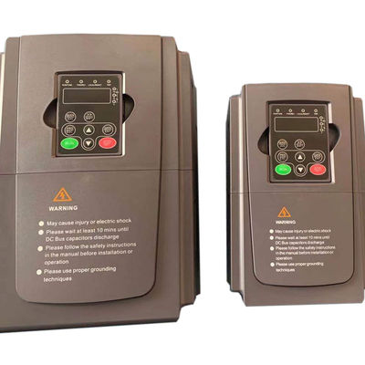
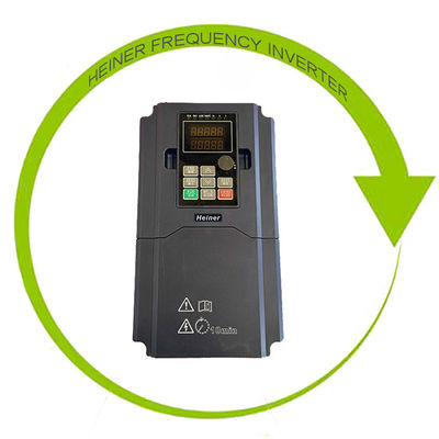
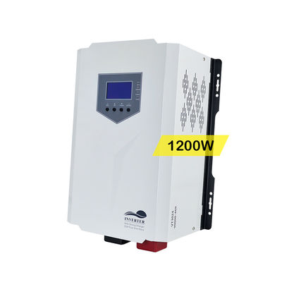
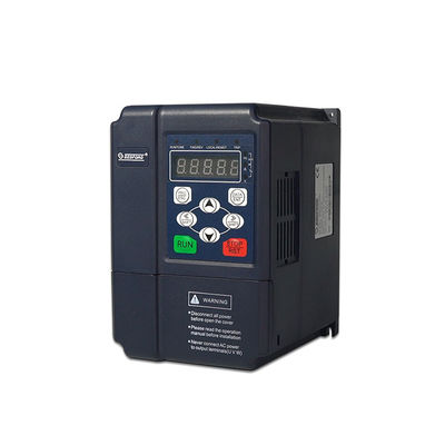
FREQUENCY INVERTER
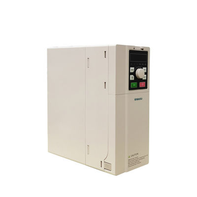
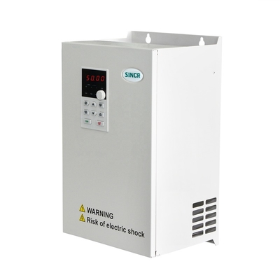
SINCR High Quality Inverter 240V To 415V 3 Phase To Single Phase Power Frequency Converter 60hz 50hz
Model | C10 & C500 Series Frequency Inverter |
Power range | 3 phase AC 380V~480V (-10% ~ +10%) 0.75KW ~ 630KW |
Output Frequency Range | 0.00~600Hz (default :50/60hz) |
Control Mode | V/F Control, Sensorless Vector Control, Torque Control |
Starting Torque | 0.5Hz/150%(SVC) |
Communication port | RS-485, which support MODBUS protocol |
Energy saving | Power saving rate 30%-80% |
PID | Built-in,Convenient to implement process control closed-loop control system ( For example: Constant pressure water supply ) |
Fault Protection | Protect from over current, over voltage, under voltage, over temperature, phase failure,over load etc. |
♦ SINCR C500 Series frequency inverter is a general-purpose High-performance current vector inverter that perfectly controls three-phase AC asynchronous motors. Built-in PID, multi-speed, simple PLC, input and output terminals, pulse frequency reference, power off and shutdown parameter storage selection, frequency reference channel and running command channel binding, dual frequency source given control, swing frequency control etc.
To provide highly integrated,all-in-one solutions for industry customers,which are extremely valuable for reducing system costs and increasing system reliability.
♦ Technical Features
♦ Product display
Model | Input Voltage/V | Power/kW | Input current /A | Output current/A | Motor/KW |
C500-0R7G-4TB | 3 Phase 380~480V | 0.75 | 3.4 | 2.5 | 0.75 |
C500-1R5G-4TB | 1.5 | 5 | 3.7 | 1.5 | |
C500-2R2G-4TB | 2.2 | 5.8 | 5 | 2.2 | |
C500-004G/5R5P-4TB | 4/5.5 | 10/15 | 9/13 | 4/5.5 | |
C500-5R5G/7R5P-4TB | 5.5/7.5 | 15/20 | 13/17 | 5.5/7.5 | |
C500-7R5G/011P-4TB | 7.5/11 | 20/26 | 17/25 | 7.5/11 | |
C500-011G/015P-4TB | 11/15 | 26/35 | 25/32 | 11/15 | |
C500-015G/018P-4TB | 15/18.5 | 35/38 | 32/37 | 15/18.5 | |
C500-018G/022P-4TB | 18.5/22 | 38/46 | 37/45 | 18.5/22 | |
C500-022G/030P-4T | 22/30 | 46/62 | 45/60 | 22/30 | |
C500-030G/037P-4T | 30/37 | 62/76 | 60/75 | 30/37 | |
C500-037G/045P-4T | 37/45 | 76/90 | 75/90 | 37/45 | |
C500-045G/055P-4T | 45/55 | 90/105 | 90/110 | 45/55 | |
C500-055G/075P-4T | 55/75 | 105/140 | 110/150 | 55/75 | |
C500-075G/090P-4T | 75/90 | 140/160 | 150/176 | 75/90 | |
C500-090G/110P-4T | 90/110 | 160/210 | 176/210 | 90/110 | |
C500-110G/132P-4T | 110/132 | 210/240 | 210/250 | 110/132 | |
C500-132G/160P-4T | 132/160 | 240/290 | 250/300 | 132/160 | |
C500-160G/185P-4T | 160/185 | 290/330 | 300/340 | 160/185 | |
C500-185G/200P-4T | 185/200 | 330/370 | 340/380 | 185/200 | |
C500-200G/220P-4T | 200/220 | 370/410 | 380/415 | 200/220 | |
C500-220G/250P-4T | 220/250 | 410/460 | 415/470 | 220/250 | |
C500-250G/280P-4T | 250/280 | 460/500 | 470/520 | 250/280 | |
C500-280G/315P-4T | 280/315 | 500/580 | 520/600 | 280/315 | |
C500-315G/355P-4T | 315/355 | 580/650 | 600/640 | 315/355 | |
C500-355G-4T | 355 | 650 | 640 | 355 | |
C500-400G-4T | 400 | 740 | 730 | 400 | |
C500-450G-4T | 450 | 850 | 840 | 450 | |
C500-500G-4T | 500 | 900 | 880 | 500 | |
C500-560G-4T | 560 | 960 | 950 | 560 | |
C500-630G-4T | 630 | 1170 | 1160 | 630 |
♦ Frequency Inverter Main circuit function description: (0.75KW-18.5KW)
Terminal | Name | Function description |
R,S,T | Inverter input terminal | Used to connect 3-phase AC power supply |
+ | DC power terminal | DC power output,(-)means DC bus cathode, (+)means DC bus anode, used for external braking unit |
- | ||
+,PB | Braking resistance terminal | Used for external braking resistance to realize quick stop |
P1,+ | DC reactor terminal | Used for external DC reactor |
U,V,W | Inverter output terminal | Used to connect the motor |
⊥ | Earth | Earth terminal, earth resistance<10 OHM |
♦ Control circuit terminals:
1.Frequency Inverter Control circuit terminal diagram:
2.Frequency Inverter control circuit terminals Function description:
Type | Terminal | Name | Function description |
Analog input | +10V | +10V power supply | Provide +10V power supply for external units,with maximum output current of 10mA.It is generally used as the operating power supply for the external potentiometer. |
AI1 | Analog input 1(reference ground:GND) | Analog input, 0~10V/ 0~20mA, switched by J4(AI1) . | |
AI2 | Analog input 2 (reference ground:GND) | Analog input, 0~10V/ 0~20mA, switched by J5(AI2). | |
GND | Common terminal of analog signal | Common terminal of analog input and output signal | |
Analog output | AO1 | Analog output 1 | Provide voltage or current output which can be switched by J1(AO1). Output range: 0~10V/ 0~20mA |
AO2 | Analog output 2 | Provide voltage or current output which can be switched by J7(AO2). Output range: 0~10V/ 0~20mA | |
GND | Common terminal of analog signal | Common terminal of analog input and output signal | |
Digital input | X1 | Multifunction input terminal | Digital signal input,The common terminal is COM. Customers could use parameter F5.01~F5.07 to set the function. While using these terminals, pls short 24V and PW. Terminal valid state Xn and COM are interlinked, Xn low level effectively. Input voltage range: 9~30V Input impedance: 3.3kΩ |
X2 | |||
X3 | |||
X4 | |||
X5 | |||
X6 | |||
X7 | |||
COM | Common ground terminal for digital signal | ||
PW | External power supply | 24V terminal is connected to PW terminal as default setting. If user need external power supply,disconnect 24V terminal with PW terminal and connect PW terminal with external power supply. | |
Digital output | HDI | High speed pulse input | High speed pulse or Digital signal input,optical coupling with PW and COM. Pulse input frequency range: 0~50kHz Input voltage range: 9~30V Input impedance: 1.1kΩ |
COM | Common ground terminal for digital signal | ||
HDO | High speed pulse output | High speed pulse output terminal. The corresponding common ground terminal is COM. Using internal 24 v power supply,the CME and COM terminal must be connect. | |
CME | Common terminal of open collector output | ||
COM | Common ground terminal for digital signal | ||
Y1 | Open collector output | The corresponding common ground terminal is CME. External voltage range: 0~24V Output current range: 0~50mA | |
Relay output | TxA | Relay1 and Relay2 | Get by the function code F6.04 and F6.05,defined as a variety of functions for Relay TxA-TxC:Normally-open contact; TxB-TxC:Normally-closed contact; Max contact capacity:AC250V/2A , DC30V/1A |
TxB | |||
TxC | |||
Communication | A+ | RS485 anode | Standard 485 interface |
B- | RS485 cathode |
♦ Variable frequency inverter applicable occasions:Fans, Pumps, 3-Phase Motors, Machine Tool, Textile, Mining, Chemical, Plastic machinery, Metallurgy, Oil, Woodworking, Pharmaceutical, Ceramics, Paper, Lifting,Printing And Packaging, Air Compressors ,Agricultural Irrigation, etc.
Shenzhen SINCREA Electrical Technology Co., Ltd.is a National&Shen zhen High-Tech enterprises specializing in electric drive,frequency inverter,industrial control,solar pump inverter,new energy products research and development, production and sales.
SINCREA's production line:low,medium and high voltage frequency inverters,servo drives,solar pump inverter,soft starters, PLC, HMI, UPS and other products. The company has passed ISO9001: 2015 quality system certification and CE certification, widely used in plastic machine, machine tool, textile, chemical, woodworking, metallurgy, mining, pharmaceutical, ceramics, paper, oil, printing, food, lifting, elevator, power and energy.
SINCREA will adhere to the market-oriented,customer-centric business philosophy,and continuously develop and improve our products to provide customers with differentiated products and services,and become a popular electric drive,new energy,and system solutions supplier.
Carton | Suitable for 0.75KW~45KW Frequency Inverter. |
Woodenbox | Suitable for ≥45KW Frequency Inverter. |
By Sea | Delivery from Shenzhen Port. |
By Express | FedEx/TNT/DHL/UPS/EMS |
Contact us for more information, we will show you professional service with best price
담당자 : | Franny |
---|